PIC mood lamp/alarm clock

In 2008-2009, we hosted an exchange student. After the first few months I started wondering, based on previous experience hosting our first exchange student five years prior, what I would give her as a going-away present when she went back to Germany. At about the same time, an older "DIY mood lamp" project was making the rounds.
I thought this might be a good fit - but it wasn't quite good enough. Initially I thought that the two of us might make this together. I realized quickly that she wasn't quite in to it at that level, and I let the project take on new dimensions.
The lamp schematics that were making the rounds weren't the way I liked things. The code wasn't written in assembly. The color shifting was effective, but crude. It wasn't nearly as configurable as I wanted it to be. Perhaps a light organ feature, too. And clearly, it should have a wake-lamp function; those things are interesting (from a physiological perspective) and relatively expensive.
Sarah didn't want a light-up lamp unless it had audible fallback. Makes sense, so I should add that. But a piezo beeping didn't seem like a good fit with the rest of the feature set - so it should play something relatively pleasant. Music, perhaps.
And with that feature set - a mood lamp that randomly changes colors, has a full-bright mode, a light organ mode that responds to ambient noise, and an alarm clock that can either wake you by light or music or both - it dawned on me that I had a timepiece that could also play any recorded audio at any time/date that I wanted. The final product has 14 birthday reminders, 44 one-time personal messages, one music alarm, and room for a hundred times more.
Okay, so I'm a bit crazy.
Warning
This is NOT complete documentation of the project and process. If you know what you're doing, this should be sufficient information to get you where you want to go. Read on at your own peril.
Design evolution
Some tidbits about the evolution of the hardware design:
- The design started with a PIC 16f628A, and progressed all the way up to a 40-pin PIC 16F877A; it needed the pin count and program memory.
- The first versions used an SD card. The final used a MicroSD card.
- Originally, the PIC implemented its own PWM engine for three colored LEDs. They were eventually replaced with the MAXM to reduce code space (and PWM cross-talk on my primitive busses).
- The circuit uses one I2C bus and two SPI busses. The former talks to the RTC and MAXM, while the SD card and D/A output are on their own SPI busses. The separation is required as I don't have the buffer space to read in 512 bytes from the SD card before de-asserting control.
- I started with simple resistor ladder D/A converters, and eventually wound up at the MPC4921 - an SPI bus device. It's very simple to use and presents very good quality 12-bit audio. I highly recommend this IC for its ease of use and excellent performance.
- I blew out the red LED on two different high-output arrays while experimenting (once was a deliberate attempt to push the LED farther than it was specified, and the other involved accidentally crossing two wires while testing). Be careful and order spares.
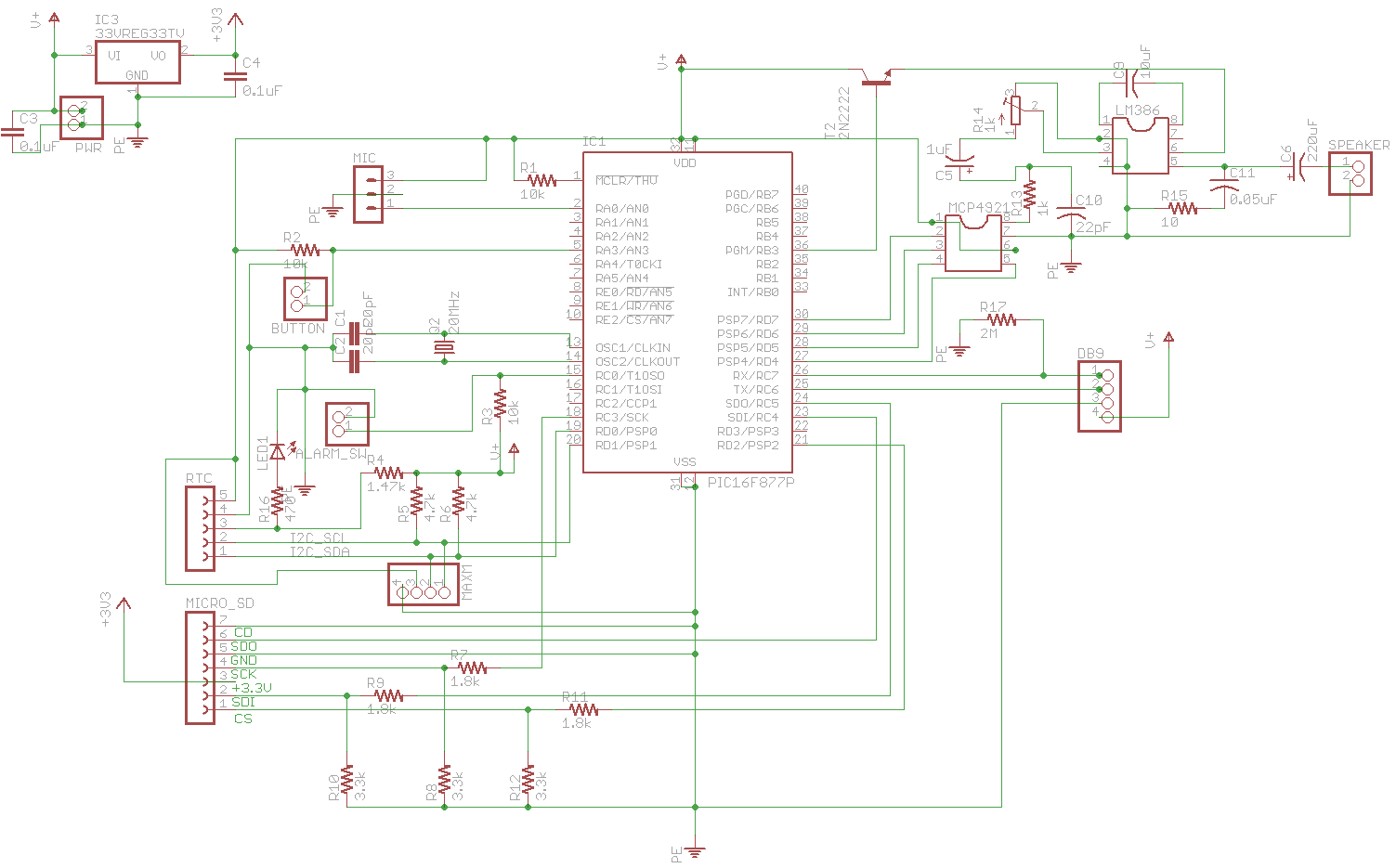
Schematics
This crude schematic documents the general circuit. Some labels aren't exactly right (e.g. the 3.3v regulator is *not* a 7805T, which would be a 5v regulator) - but it was close enough for what I was doing. I also changed horses on the mic at the last minute and forgot to attach the latest revision of the mic input board to the circuit before affixing it in place, so the final lamp doesn't have a color organ mode (although the code references it).
Parts List
- lamp ($15 desk lamp from Home Depot)
- 3.3v regulator (sparkfun.com COM-00526)
- R1,R2,R3 10k 1/4w
- R4 1.47k 1/4w
- R5, R6 4.7k 1/4w
- R7,R9,R11 1.8k 1/4w
- R8,R10,R12 3.3k, 1/4w
- R13 1k, 1/4w
- R14 1k trim pot
- R15 10, 1/4w
- R16 470 1/4w
- R17 2M, 1/4w
- Not shown: three 12-15 ohm 1W power resistors (from MaxM to LEDs)
- C1, C2 20pF
- C3, C6, C9 10uF
- C4, C5, C7 1.0uF
- C8 220uF
- C10 22pF
- C11 0.05uF
- LM386 (digikey.com)
- MCP4921 (digikey.com)
- MAX232CPE (maxim-ic.com)
- PIC16F877P (digikey.com)
- 1 momentary pushbutton
- 1 SPST toggle switch
- Q1 20MHz xtal
- LED1 red LED
- Not shown: 3-watt RGB LED, common anode (found some at bestofferbuy.com - search for "3W LED Emitter on Star" )
- Not shown: aluminum CPU heatsink I had lying around
- RTC (sparkfun.com BOB-00099)
- BlinkM MAXM (sparkfun.com COM-09000, but just the controller board)
- MicroSD breakout board (sparkfun.com BOB-00204)
- Speaker (sparkfun.com COM-09151)
- Not shown: 3" acrylic ball, sawed in half, serving as a diffuser
Other Documentation
Software dependencies
To build this, you'll need:
- gcc, make
- Perl
- gplink, gpasm
- picp
- pic-disassemble (only for analysis purposes)
SD card bugs
I've noticed that the SD code I've written must have a bug in its initialization routine. It works on some devices, but not all. I'm using it with a SanDisk 2GB MicroSD card.
Update, November 2010: I've found and fixed problems with the initialization routine. I'm now using this with various 1 and 2 GB MicroSD cards successfully.
BlinkM MaxM operation
The MaxM includes built-in "programs". The lamp uses those to make its job easier. But you have to get the programs into the MaxM, and I didn't like the idea of continually rewriting the program every time the lamp was unplugged. To write the program once, you'll have to change an "#if 0" in maxm.asm to "#if 1" and power up the lamp.
Physical build
The LEDs sit on a heatsink in the lamp body. Wires run back under the heatsink into the lamp base. The acrylic ball (which I got from mcmaster-carr.com, but had to order a dozen in order to get one) covers the LED assembly to both diffuse the light and prevent objects from falling on the (very hot) LED assembly. The in-lamp assembly is held together with silicone caulk, which will stand up to the temperature well.
In the base, a thin sheet of cardboard serves as an insulator between the circuit board and the top (lamp side) of the metal base. The circult is caulked to that board. I also wound up reusing parts of the original base bracket, now caulked to the sides of the lamp, to reattach the base plate. I also fashioned a third support to improve stability.
Holes were drilled in the base plate where the speaker sits (to allow sound to flow out of the lamp), and rubber feet attached to the bottom of the lamp in order to improve sound quality.
Misc.
The source code is available on github.com
A universal 110-220 5V 2A power brick was added to power the device.